Our article as published "In my Opinion" in the March 2015 issue of Microwave Product Digest.
Attenuators on VNA Cables when testing Passive Devices
Some difficulty in
acquiring reliable measurements triggered a point of interest from previous
experiences. Why did some technicians place
precision attenuators on one or both VNA cables as part of a setup for
measuring passive devices? “It’s always been there.” But like all things, there must be a reason.
Protection of
equipment from power overload sensibly applies to active devices. Since I had been employed at companies that
manufactured both active and passive devices, I wondered if it was merely
convenient to leave it on all the time.
But what effect would this have on production testing of passive
devices? And what advantages or problems,
if any, come from this?
A question on Linked
In quickly erupted into an elaborate, technical discussion about the benefits
and drawbacks of calibrating through precision attenuators on VNA cables. I thank all those who contributed their
insight. Following this, I experimented
on the subject, to arrive at some conclusion on the effect of calibration and
production testing. More importantly,
how it might help improve reliability of measurements with our VNA.
The characteristic
return loss of any cable contains ripple; and this becomes more pronounced with
length. Of course, the lower to the
noise floor this ripple is, the better.
But even with lower grade cables, the VNA calibration sets the reference
planes beyond the cable, thereby eliminating this from the measurement. Or does it?
The importance of
phase and amplitude stability is emphasized in the quality of the test
cables. As vectors are comprised of
magnitude and phase, an unexpected variation would invalidate measurements. Bending and flexing a cable, even slightly
will introduce a variation against the calibrated values. Not to mention temperature and humidity
drifting. And when an imperfect DUT is
introduced, the problem compounds.
An indoor office
environment can be made relatively stable, at least for a timeframe long enough
to acquire measurements. So I am not too
worried about temperature and humidity fluctuations immediately following
calibration. However, slight bends in
cables are unavoidable, particularly when DUT ports are located on several
different mounting faces. Fixtures can
aid. We found clamping the cable gently
in a vise during and after calibration to be particularly helpful in securing
cables while minimizing bends.
That being
established, we conducted some experiment to observe the ripple effect, and answer
the question as to the benefit, if any, provided by calibrating through
attenuators on VNA cables.
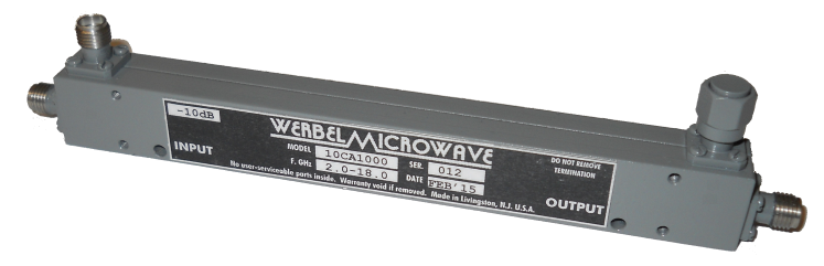
In the experiment, we
considered both 2-way and 4-way Wilkinson power dividers and a 10-dB
directional coupler of our own design covering 2-18GHz, a pair of 3-foot test
cables, and a pair of 10-dB attenuators specified to 18GHz.
In the first pass, an
SOLT calibration was performed using both cables only. With the 2-way splitter connected directly, VSWR
measured 1.4:1 or better at all ports, which is reasonable and expected for the
DUT. However, there was noticeable
ripple of many peaks in the through measurement, superimposed upon the expected
characteristic ripple caused by multiple Wilkinson sections.
We then measured our
4-way model. There was still some cable-induced
ripple present, but less pronounced, down at -6.5dB. When we measured a precision -10dB
attenuator, or our 10-dB directional coupler model for that matter, the ripple
was barely noticeable. So for us, this
was a problem when measuring relatively low-value attenuation.
The VNA was then
recalibrated SOLT with 10-dB precision attenuators on each cable end that would
interface to the DUT. It is important to
note the attenuators remained as part of the test set for the entire
calibration. The 2-way DUT was
reconnected with the padded cables. VSWR
was identical to the non-cable measurements, thereby verifying the
calibration. The cable-induced ripple
was almost non-existent, except at the highest frequencies (above 13-GHz,
probably beginning to cross over the attenuator element despite being rated to
18-GHz).
We performed one more
experiment using a connector saver adapter so the DUT could be connected
directly onto the VNA port 1, using only one cable without attenuator on port
2. As with the first experiment, there
was ripple at -3.5 and -6.5 dB, but not as pronounced as with two, unpadded
cables.
It would appear to me
that even though the SOLT calibration cancels out the effect of cable ripple
initially, when reflections exist on the line caused by an imperfect DUT or
cable flexure, these reflections get summed with the ripple of the cable, and
are reintroduced into the measurement. The
attenuators proved to be a useful ripple buffer in taking S21 measurements at
the expense of a reduction in dynamic range.
In fact, there was noticeable noise appearing in S11 and S22 windows as
high as -40dB, making this approach impractical for high-attenuation DUT’s such
as our upcoming 50-dB directional coupler.
Of course, using a
large smoothing aperture when recording passband ripple is cheating, and nobody
ever does that. An improvement to the
setup perhaps, will be to use lower value attenuators, such as 6-dB or even
3-dB, to assist in clean, passive measurements without the use of smoothing. Please write to me with your comments and
suggestions.
Ernest Werbel
Werbel Microwave LLC